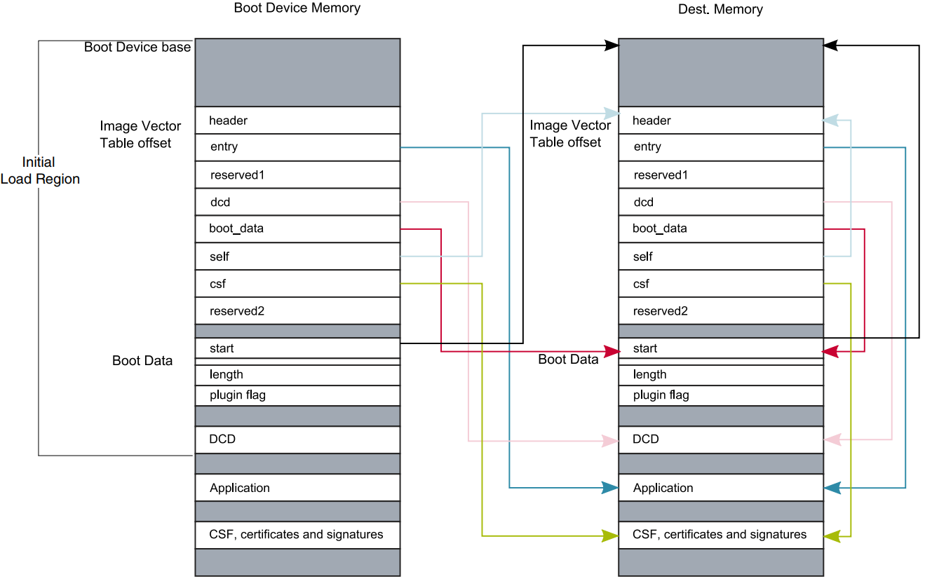
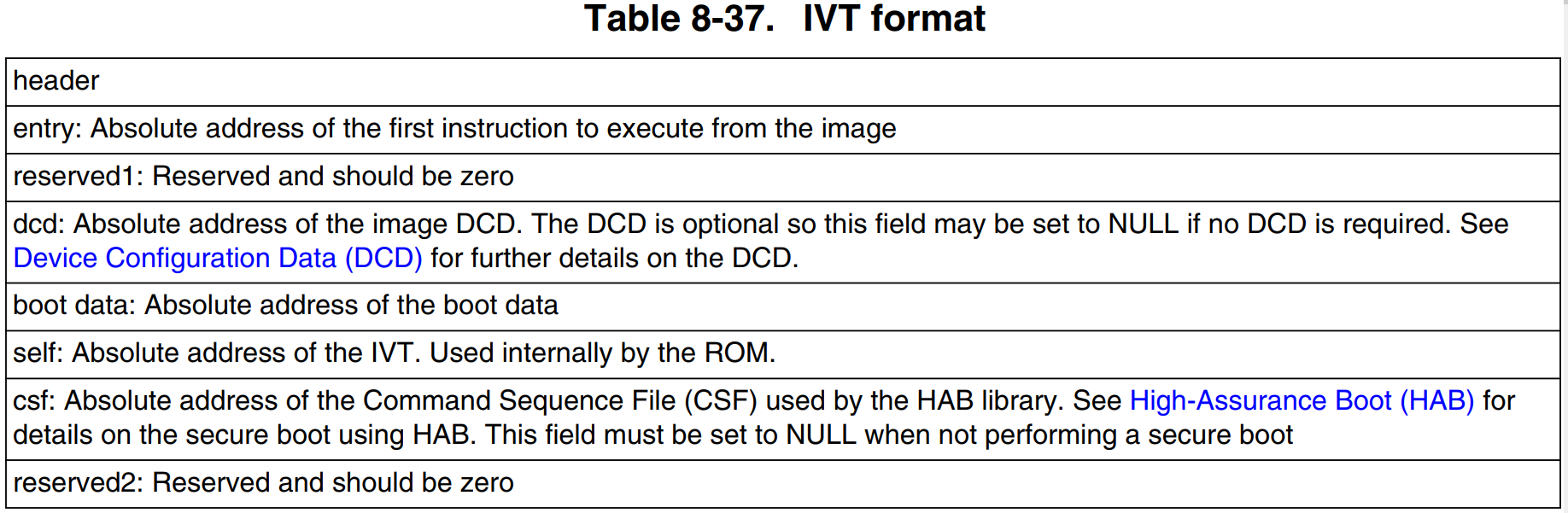
/************************************* * IVT Data *************************************/ const ivt image_vector_table = { IVT_HEADER, /* IVT Header */ IMAGE_ENTRY_ADDRESS, /* Image Entry Function */ IVT_RSVD, /* Reserved = 0 */ (uint32_t)DCD_ADDRESS, /* Address where DCD information is stored */ (uint32_t)BOOT_DATA_ADDRESS, /* Address where BOOT Data Structure is stored */ (uint32_t)&image_vector_table, /* Pointer to IVT Self (absolute address */ (uint32_t)CSF_ADDRESS, /* Address where CSF file is stored */ IVT_RSVD /* Reserved = 0 */ };
__attribute__((section(".boot_hdr.boot_data")))
/************************************* * Boot Data *************************************/ const BOOT_DATA_T boot_data = { FLASH_BASE, /* boot start location */ FLASH_SIZE, /* size */ PLUGIN_FLAG, /* Plugin flag*/ 0xFFFFFFFF/* empty - extra data word */ }; #endif
3、FlexSPI接口配置
The ROM expects the 512-byte FlexSPI NOR configuration parameters as explained in next section to be present at offset 0 in Serial NOR flash. The ROM reads these configuration parameters using the read command specified by BOOT_CFG2[2:0] with Serial clock operating at 30 MHz.
In the second step, ROM configures FlexSPI interface with the parameters provided in configuration block read from Serial NOR flash and starts the boot procedure. Refer to Table 8-17 for details regarding FlexSPI configuration parameters and to the FlexSPI NOR boot flow chart for detailed boot flow chart of FlexSPI NOR.
Upon reset, the chip uses the default register values for all peripherals in the system.However, these settings typically are not ideal for achieving the optimal system performance and there are even some peripherals that must be configured before they can be used.
The DCD is a configuration information contained in the program image (external to the ROM) that the ROM interprets to configure various peripherals on the chip.For example, some components (such as SDRAM) require some sequence of register programming as a part of the configuration before it is ready to be used. The DCD feature can be used to program the SEMC register to the optimal settings.
The ROM determines the location of the DCD table based on the information located in the Image Vector Table (IVT). See Image Vector Table and Boot Data for more details. The DCD table shown below is a big-endian byte array of the allowable DCD commands. The maximum size of the DCD is limited to 1768B.